LED POSITION LIGHTS
For
EXPERIMENTAL
AIRCRAFT
After looking at the prices of certified position lights for my RV-7 (about $200 a pair) I looked into the possibility of building my own using high-brightness LEDs. After doing a bit of research into the FAA requirements and then into the available high-brightness LEDs, (These are NOT ordinary LEDs.) I concluded it could be done for less than the cost of “store bought” position lights. I then made a computer model of the FAA candlepower distribution requirements and the light distribution of each LED. After a bit of tinkering, the model produced the proper layout for the array of LEDs needed to meet the FAA specifications.
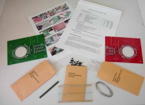
Each kit contains all the parts you need
(including the LEDs, regulators, and circuit boards) to build both a red and a
green position light. Also included are instructions and solder.
There are three styles of boards.
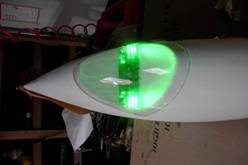
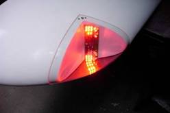
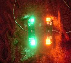
The “RV Style” long, thin, rectangular boards (4.5” x 1.43”) are specifically designed to fit in the sheared wingtips of Vans aircraft. These are designed to fit in the inside corner of the sheared wingtip against the back surface so that you can mount Bill Von Dane’s landing lights in the wingtip as well. http://www.creativair.com/ The components are mounted toward the inboard edge so that you can shave away some of the center of the board if you need additional clearance for a slightly larger landing light.
Notice that the LEDs are mounted on the top
and bottom of the board. This allows you to mount a strobe ahead of the board
(on the outward-facing surface within the sheared tip) and not block any of the
light.
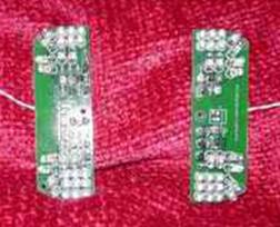
The
square style of board is shown below:
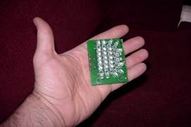
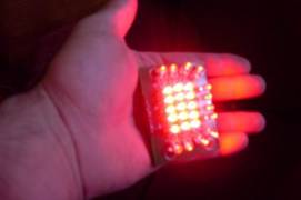
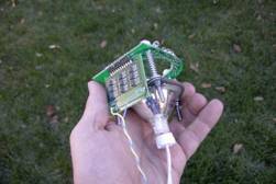
These compact square boards have the
regulator section (optionally) wrapped around the back to give a minimum size
of 2.25” x 1.6”.
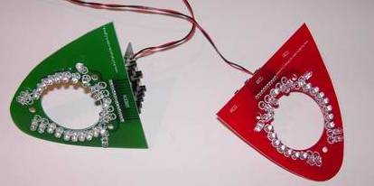
The newest style is the “Combo Light” style.
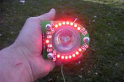
These are designed to integrate directly with CreativAir landing lights. They are the most compact and lightweight lighting system available. They can be shaped to fit the tinyest of sheared tips, even the LancAir IV (shown above). They can also be shaped to fit much larger sheared wingtips like the RV-7 (shown below.)
For wingtips larger than the RV-7 (like the RV-9 and RV-10) the green (or red) circuit board may not be quite large enough to cover the entire rear surface area of the sheared tip. For these wingtips, it is best to trim the board to leave a uniform edge border.
Prices:
$120 + $5 S&H for: LED
Position Light Kit (All the parts for both a red and a green
light.) Specify long or square boards.
RV Style $125 total
Click
HERE to Buy Now via PayPal
Square Style $125 total
Click
HERE to Buy Now via PayPal
Add $2 if you want a Soldering
Practice Kit. (Recommended for those new to electronic
assembly.) Add $2
Add $75 for each kit if you want
me to assemble it for you.
RV Style Assembled $200 total
Click
HERE to Buy Now via PayPal
Square Style Assembled $200 total
Click
HERE to Buy Now via PayPal
Assembled Combo Style Position Light (not trimmed to shape) alone (no Landing Light) Kit $232 total
I ship on Saturday.
If you wish to pay by check or money order
send to:
Bill Dube’
4680 Miller St
Wheat Ridge, CO 80033
There will be a delay of two weeks after I
receive the check.
E-mail me at LED@KillaCycle.com if you have questions.
Additional
Information
Each complete position light weighs just 24
grams! The pair of lights draw just 0.5 amps total.
Both types of boards are designed for the
surface of the board to be facing forward in the direction of travel.
All the LEDs are carefully angled to give the
required candlepower in each direction. The FAA requires that there be at least
40 candlepower directed straight ahead, tapering to 5 candlepower to the sides,
and considerably less above and below the centerline. That is why most of the
LEDs are directed straight forward and only a few are directed at large angles
to the side, top, and bottom.
Being a typical engineer, I designed in a
significant extra margin so the measured light output of the finished prototype
exceeded the FAA minimums by at least 10% in all directions and exceeded the
FAA minimums by as much as 50% in some directions.
The red LEDs produce more light per watt than
the green LEDs. Thus, the red position light only draws about 0.2 amps. The
green side draws about 0.3 amps. Typical incandescent position lights are 27
watts each and draw a little over 4 amps for the pair. Obviously the LED units
are much, much more efficient. One of the big differences is that the LEDs
produce only the exact wavelength needed while the incandescent lamps produce a
wide spectrum that must be filtered down to just the color needed. Thus, most
of the wattage is blocked and thrown away by the filter lens.
These boards have the current regulators that
hold a steady current though each of the LEDs. This makes the light output
steady regardless of fluctuations in the voltage supplied by the airplane.
These position lights will work on any voltage between 10 and 30 VDC. (The
CreativAir landing lights are available in 24 volt at an additional cost.)
There is quite a bit of redundancy built into
these units. I took a “belt and suspenders” approach in the design. Instead of
using a single voltage regulator for the whole light, I opted for multiple
current regulators controlling small groups of the LEDs. In that way, only a
few of the LEDs will go dark if a component fails. Quite a few components would
have to fail to make the light go completely dark.
LEDs typically last 100,000 hours, so you
won’t be changing any bulbs very soon, likely never.
If you want to read the assembly instructions
for the LED Position Lights Kit, click->
http://www.killacycle.com/Instructions.htm
If you want to see a square board installed on
an F1 Rocket, take a look at Bob Gross’s installation at
http://www.f1-rocketboy.com/led.htm
Custom Layout
A lot of folks have been asking me about
rearranging the layout of the LEDs to fit their specific aircraft. This is not
as simple as using the stock board layout, but there is a great deal of
flexibility if you need it and are willing to make a little extra effort. You
don’t HAVE to mount the LEDs on the board.
The LEDs can be mounted almost anywhere as
long as each one is pointing in the required direction (azimuth and elevation,)
nothing blocks the view directly in front of them, and you don’t alter the lens
on the tip of the LED.
I have done the hard part by selecting the
correct LEDs, calculating the correct angles, designing the regulator board,
and putting together the kit.
If you want to mount the LEDs yourself, the
square board kit is the best option. This is because the regulator section is
separated from the LED section. The board is set up for these two halves to be
physically separated and electrically connected by an in-line header. You can
replace the header with a ribbon cable, you can toss the LED portion of the
board, and wire the LEDs to the ribbon cable, kind of like Christmas tree
lights. Then you can mount them anywhere you like. Simply use the stock LED
board as a guide to set the angle for each of the LEDs.
Since the LEDs have a typical lifespan of
100,000 hours, it is a safe bet that you will not have to replace them, ever.
Thus, you can mount them somewhat permanently, unlike incandescent lamps. This
opens a whole new world of mounting possibilities.
Contact me at LED@KillaCycle.com if you have questions
or need help with a custom layout.